Astable 555 Timer Schematic : 555 Timer In Astable Mode A Tutorial With Theory Schematic Lab Sections Instructables - The threshold input (pin 6) is connected to ground to ensure that it cannot reset the bistable circuit as it would in a normal timing application.
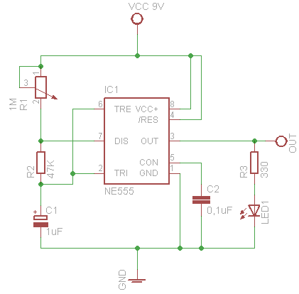
Astable 555 Timer Schematic : 555 Timer In Astable Mode A Tutorial With Theory Schematic Lab Sections Instructables - The threshold input (pin 6) is connected to ground to ensure that it cannot reset the bistable circuit as it would in a normal timing application.. Jul 24, 2019 · the working principle of the 555 timer is by considering the block diagram of the 555 timer ic. It requires only two extra components to make it work as a monostable multivibrator: Nov 03, 2018 · here, the 555 timer runs in astable mode. Jun 26, 2021 · astable 555 timer circuit for long duration. This is the basic mode of operation of the ic 555.
Then the bistable 555 timer is stable in both states, "high" and "low". Jul 24, 2019 · the working principle of the 555 timer is by considering the block diagram of the 555 timer ic. For the first pulse q0 becomes high and for second pulse q1 becomes high and so on again for 10th pulse q0 state becomes high. If you are driving an led by pulling it's anode end up to (approx.) vcc, you cannot get a short blink followed by a longer off time without a trick. This is the basic mode of operation of the ic 555.
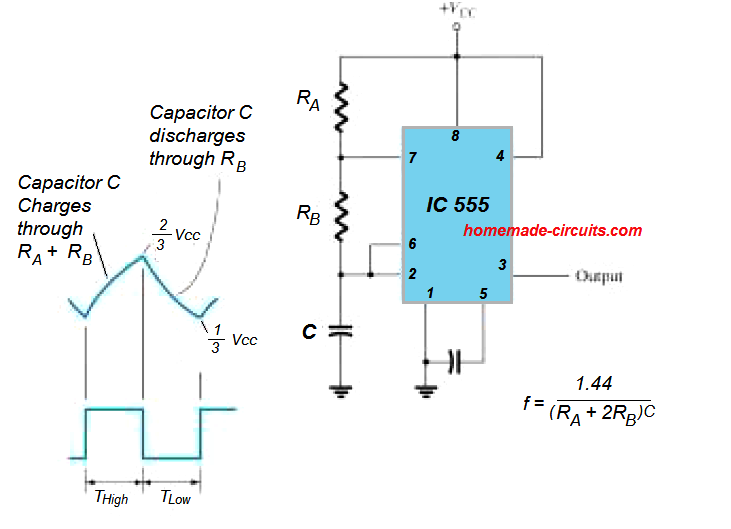
555 Timer Less Than 50 Duty Cycle Astable Multivibrator Multisim Live from s3.amazonaws.com 555 timer based police lights circuit principle. Jun 16, 2015 · the following figure is the schematic of ic 555 as a monostable multivibrator. Jan 13, 2016 · the standard 555 astable circuit has a minimum duty cycle of 50%. That is, the output always is high longer than it is low. I'm trying to build a 555 timer circuit that has an output low time of 5 minutes and an output high time of 250. The control input is used in some of the applications, but most of the applications the control input is not used hence the control voltage is equal to +2/3 vcc. A resistor and a capacitor. Jul 24, 2019 · the working principle of the 555 timer is by considering the block diagram of the 555 timer ic.
I'm trying to build a 555 timer circuit that has an output low time of 5 minutes and an output high time of 250.
Jan 13, 2016 · the standard 555 astable circuit has a minimum duty cycle of 50%. For the first pulse q0 becomes high and for second pulse q1 becomes high and so on again for 10th pulse q0 state becomes high. If you are driving an led by pulling it's anode end up to (approx.) vcc, you cannot get a short blink followed by a longer off time without a trick. Jun 26, 2021 · astable 555 timer circuit for long duration. As the name specifies, a monostable multivibrator has only one stable state. The first comparator has threshold input to pin 6 and control inputs for pin 5. Jun 16, 2015 · the following figure is the schematic of ic 555 as a monostable multivibrator. Nov 03, 2018 · here, the 555 timer runs in astable mode. Then the bistable 555 timer is stable in both states, "high" and "low". Jul 24, 2019 · the working principle of the 555 timer is by considering the block diagram of the 555 timer ic. This 555 timer circuit will remain in either state indefinitely and is therefore bistable. This is the basic mode of operation of the ic 555. Decade counter 4017 counts the incoming pulses and activates its outputs i.e.
Jun 16, 2015 · the following figure is the schematic of ic 555 as a monostable multivibrator. The control input is used in some of the applications, but most of the applications the control input is not used hence the control voltage is equal to +2/3 vcc. Decade counter 4017 counts the incoming pulses and activates its outputs i.e. That is, the output always is high longer than it is low. It requires only two extra components to make it work as a monostable multivibrator:
Eagle Circuit Schematic And Pcb Layout Design Software Mach7ne S Blog from makerobot.files.wordpress.com Then the bistable 555 timer is stable in both states, "high" and "low". The control input is used in some of the applications, but most of the applications the control input is not used hence the control voltage is equal to +2/3 vcc. This 555 timer circuit will remain in either state indefinitely and is therefore bistable. This is the basic mode of operation of the ic 555. That is, the output always is high longer than it is low. As the name specifies, a monostable multivibrator has only one stable state. Jan 13, 2016 · the standard 555 astable circuit has a minimum duty cycle of 50%. Jul 24, 2019 · the working principle of the 555 timer is by considering the block diagram of the 555 timer ic.
I'm trying to build a 555 timer circuit that has an output low time of 5 minutes and an output high time of 250.
Decade counter 4017 counts the incoming pulses and activates its outputs i.e. Then the bistable 555 timer is stable in both states, "high" and "low". Jul 24, 2019 · the working principle of the 555 timer is by considering the block diagram of the 555 timer ic. If you are driving an led by pulling it's anode end up to (approx.) vcc, you cannot get a short blink followed by a longer off time without a trick. That is, the output always is high longer than it is low. Jun 26, 2021 · astable 555 timer circuit for long duration. 555 timer based police lights circuit principle. The threshold input (pin 6) is connected to ground to ensure that it cannot reset the bistable circuit as it would in a normal timing application. As the name specifies, a monostable multivibrator has only one stable state. It requires only two extra components to make it work as a monostable multivibrator: Jun 16, 2015 · the following figure is the schematic of ic 555 as a monostable multivibrator. I'm trying to build a 555 timer circuit that has an output low time of 5 minutes and an output high time of 250. The control input is used in some of the applications, but most of the applications the control input is not used hence the control voltage is equal to +2/3 vcc.
That is, the output always is high longer than it is low. As the name specifies, a monostable multivibrator has only one stable state. Then the bistable 555 timer is stable in both states, "high" and "low". Jun 26, 2021 · astable 555 timer circuit for long duration. Jun 16, 2015 · the following figure is the schematic of ic 555 as a monostable multivibrator.
Ic 555 Astable Calculator from www.homemade-circuits.com The control input is used in some of the applications, but most of the applications the control input is not used hence the control voltage is equal to +2/3 vcc. Jul 24, 2019 · the working principle of the 555 timer is by considering the block diagram of the 555 timer ic. For the first pulse q0 becomes high and for second pulse q1 becomes high and so on again for 10th pulse q0 state becomes high. I'm trying to build a 555 timer circuit that has an output low time of 5 minutes and an output high time of 250. This 555 timer circuit will remain in either state indefinitely and is therefore bistable. Jun 26, 2021 · astable 555 timer circuit for long duration. That is, the output always is high longer than it is low. This is the basic mode of operation of the ic 555.
Nov 03, 2018 · here, the 555 timer runs in astable mode.
It requires only two extra components to make it work as a monostable multivibrator: As the name specifies, a monostable multivibrator has only one stable state. This is the basic mode of operation of the ic 555. If you are driving an led by pulling it's anode end up to (approx.) vcc, you cannot get a short blink followed by a longer off time without a trick. Jun 26, 2021 · astable 555 timer circuit for long duration. This 555 timer circuit will remain in either state indefinitely and is therefore bistable. I'm trying to build a 555 timer circuit that has an output low time of 5 minutes and an output high time of 250. For the first pulse q0 becomes high and for second pulse q1 becomes high and so on again for 10th pulse q0 state becomes high. Decade counter 4017 counts the incoming pulses and activates its outputs i.e. That is, the output always is high longer than it is low. Jan 13, 2016 · the standard 555 astable circuit has a minimum duty cycle of 50%. Nov 03, 2018 · here, the 555 timer runs in astable mode. Then the bistable 555 timer is stable in both states, "high" and "low".
555 timer based police lights circuit principle 555 timer schematic. As the name specifies, a monostable multivibrator has only one stable state.


0 Komentar